Controlling Motor || LED Blinking using Button with Arduino||TinkerCad Simulation
Description:
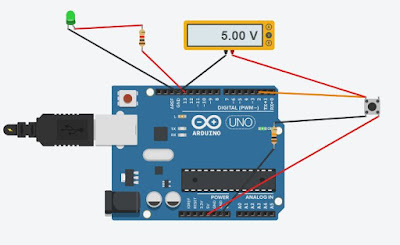
This Experiment is based on the different component integrated to blink the LED using Button. we also look on how voltage flow from the digital pins and use voltmeter to measure the flowing current through the digital pin as the below picture described.
 |
| Peepgram fig 1 |
Below the Circuit of the Experiment perform in this very lecture. we have connected different components using Red & Black wires for instant Red is given to the Power wires and Black given to the Ground Wires. LED is used is Green light Button is also connected. Pins we have used for input we configure digital pin 2 and for output we have configured digital pin 13 as shown below you can see the Resistance connected to the ground of the button it called Push Down Resistance which save our pins form over flow in a simple words:
 |
| Peepgram fig 2 |
Voltmeter connected to check our output of the button how much current from when i press the button:
 |
| Peepgram fig 3 |
 |
| Peepgram fig 4 |
 |
| Peepgram fig 5 |
int state=0;
void setup()
{
pinMode(13, OUTPUT);
pinMode(2,INPUT);
}
void loop()
{
state=digitalRead(2);
if(state==HIGH)
{
digitalWrite(13, HIGH);
}
else
{
digitalWrite(13, LOW);
}
}
click for more help:

Post a Comment